
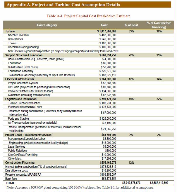
Preface: The Department of Energy high wind penetration plans require a lot of offshore wind. But is it possible, affordable, or wise to do this? Corrosion leads to a short lifespan of just 15 years. To reduce maintenance, offshore windmills use limited rare earth metals. A 500 MW offshore wind farm could cost $3.04 Tillion dollars (Table A-1). The materials (i.e. steel & concrete) needed for 730,099 2 MW windmills in America are staggering. Offshore turbines of 6 MW weigh 757 tons, nearly 2.5 times more than onshore turbines (table 4.3), each one weighing as much as 505 cars of 3,000 pounds each. The latest proposed turbines in New Jersey will be 800 feet tall (Grandoni 2020). Most components are made in China and Europe, so supply chain disruptions would delay repairs or repowering.
Wind turbines can be battered, rusted, corroded, or destroyed by tides, storms, hurricanes, lightning, icebergs, floes, large waves, and marine growth, shortening their lives and increasing maintenance and operation costs.
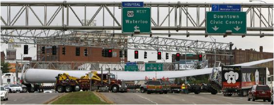
Offshore wind turbines are often stood upright on ships and moved to their location, which can’t be done if there are any bridges in the way. The U.S. only has five utility-scale wind turbines in 2021, all off of Rhode Island.
Why build risky, expensive, short-lived offshore wind farms if a renewable electric grid may not be possible given the lack of a national grid, lack of commercial-level utility-scale energy storage, and the insurmountable issue of seasonal wind and solar? Peak oil occurred in 2018, so sometime within the next 10 years oil shocks will hit and oil will be too precious for building such contraptions, and eventually be rationed mainly to agriculture as the 1980 DOE Standby rationing plan called for, and after that, the center will not hold. Rather than wind turbines, remaining energy should be used to go back to organic (regenerative) agriculture, burying nuclear wastes, and myriad other efforts for going back to Wood World for energy and infrastructure, like all civilizations before fossils.
Floating offshore wind turbines
Offshore wind turbines are limited to water at most 165 feet deep. Some 60% of available offshore wind resource in the U.S. is beyond the reach of fixed-bottom foundation turbines, including most of the West Coast.
The only commercial floating wind farm today is in Hywind Scotland. each Siemens SWT-6.0-154 turbine has a towerhead mass of around 350 tons and sits on a foundation with roughly 6,060 tons of solid ballast and a displacement of some 13,230 tons. The turbine is attached to a spar buoy that extends 260 feet below the surface and tethered up to 390 feet below (Deign 2020).
Alice Friedemann www.energyskeptic.com author of “When Trucks Stop Running: Energy and the Future of Transportation”, 2015, Springer, Barriers to Making Algal Biofuels, and “Crunch! Whole Grain Artisan Chips and Crackers”. Podcasts: Collapse Chronicles, Derrick Jensen, Practical Prepping, KunstlerCast 253, KunstlerCast278, Peak Prosperity , XX2 report
***
Navigant. 2013. U.S. Offshore Wind Manufacturing and Supply Chain Development. U.S. Department of Energy.
https://www1.eere.energy.gov/wind/pdfs/us_offshore_wind_supply_chain_and_manufacturing_development.pdf
Can we afford offshore wind turbines? A 500 MW farm costs $3 trillion dollars and will last only 15 years
| Component | Land-basedtons | Offshoretons |
| Rotor | 62 | 156 |
| Nacelle | 82 | 316 |
| Tower | 162 | 285 |
| Total Assembly | 306 | 757 |
Table 4-3. Comparison of Major Land-based and Offshore Turbine Component Weights (tons)
Developing offshore wind in the U.S. introduces the issues such as:
- Hurricane risk along the southern portions of the Eastern seaboard and Gulf Coast regions, especially extreme wind gusts. Extreme loads might also result from hurricane-generated waves, sustained high winds, increased wave frequency, rapid directional wind changes, and other forces
- Surface and blade icing in the freshwater Great Lakes and other northern latitudes. Icing risks primarily manifest in the form of surface ice, which can place significant additional loads on turbine foundations and towers.
- Freshwater surface-ice floes will be a major design driver for any offshore turbines.
- Potential for earthquakes and higher average sea-states may increase fatigue concerns on offshore wind turbine structures.
- Bearings are subject to a high level of stress over the lifetime of the turbine, and therefore represent significant risk in the case of unexpected failure. This is particularly the case for offshore wind turbines, where downtime and difficult access for maintenance can have expensive repercussions.
- Towers are too heavy to move from inland locations. Single-car weight limits for U.S. railroads are approximately 140 tons (BNSF 2012, Union Pacific 2012). 5 to 6-MW turbines range from 280-325 tons.
- Wider-bases for offshore wind towers may exceed underpass requirements for either rail or road transportation. Towers for today’s 80-meter land-based turbines (with diameters of 4.5 meters) already encounter difficulties when it comes to planning trucking routes, and next-generation land-based towers (105-meters tall and 5.4 meters in diameter) are likely to face even more restrictions (AWEA 2012). Offshore wind turbine towers are likely to range from 5 to 6.75 meters in diameter.
- In addition to traffic congestion, overland transport of wind turbines can cause road damage, due to the repeated passage of heavy-load convoys. Moving wind turbine components also requires increasingly complex coordination. Scheduling between trucking companies, railroad and port operators, and city and state authorities can be very onerous. Moreover, as components grow larger, transportation costs will increase.
- Reliability is more critical offshore than onshore due to multiple factors. The offshore environment can be much harsher, with high winds, significant wave loads, and corrosion-producing salt water. Offshore turbines must be manufactured to be able to withstand this environment.
- Harsh weather offshore not only threatens the performance of wind turbines, it can also inhibit access to turbines by maintenance staff. The inability to reach and repair sub-performing or inoperable turbines can cause significant lost power sales. Severe weather also increases safety concerns for maintenance crews.
- Compared to the land-based wind market, the offshore wind market entails many more risks that increase the level of quality needed. The marine environment can be much harsher than a land-based site. Corrosion can damage external as well as internal areas of the turbine. Moreover, access constraints to an offshore site, often caused by poor weather or lack of availability of appropriate vessels, can increase O&M costs as well as reduce revenue due to power losses.
Other capital costs
- Specialized vessels to install turbines offshore can cost $100 to $250 million each. Three primary types of vessels are used in the installation of offshore wind turbines and foundations – heavy-lift vessels combined with working barges; jack-up barges without propulsion; and self-propelled jack-up vessels. In addition, subsea cable installation requires a specialized type of vessel. The continuing trend toward larger offshore turbines adds uncertainty (e.g., what size or type of vessel to construct) for investors and companies looking to build new ships to serve the offshore market.
- Land cost. Fabrication and construction need to be near or along the shore because offshore turbines are too large and heavy to move overland, and require a large amount of land
- $1.3 billion port facility. Includes blade, nacelle, tower, and foundation manufacturing facilities; new cranes, heavy-capacity terminals, staging areas, warehouse space, and infrastructure to connect to land-based transportation. $150 million for dredging and wharf reinforcements, $500 million for new infrastructure, including berthing space, storage area, and staging area; and nearly $50 million to improve lift capacity. An additional $700 million investment is assumed to go toward industrial manufacturing facilities. In addition to the blade and nacelle facilities included in the mid scenario, the high scenario includes a $240 million tower manufacturing plant and a $190 million foundation manufacturing facility.
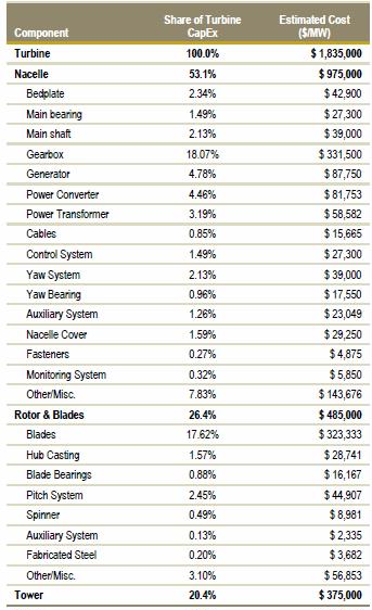
Table D-7. Per-MW Turbine Component Costs for Hypothetical U.S. Offshore Wind Project. A 6 MW turbine would cost $11 million, this doesn’t include the substructure/foundation, electric cables, substation, etc
Offshore wind limited by supplies of rare earth metals
This study reveals the need for permanent magnet generators (PMGs), and a concern this could lead to exhausting limited supplies of rare earth metals Neodymium (Nd), Dysprosium (Dy) and Praseodymium (Pr), used by the PMGs, which serve the function of making the gearbox robust enough to overcome extreme marine conditions and withstand torques, extreme forces, operating speeds, and temperatures. Global demand may reach 12,200 tons per year of rare earth metals for PMGs by the end of 2016, yet only 7,840 tons of neodymium and 112 of dysprosium are produced per year now.
The enormous size of offshore wind turbines and their components is anticipated to make it increasingly difficult, if not impossible, to move turbine components over land.
Because of this, coastal manufacturing of blades, nacelle, tower, foundation, and substructure fabrication may be an industry requirement in the near future. This will require very large swaths of coastal land—Vestas’ recently abandoned Sheerness U.K. proposed facility was planned to be on the order of 70 hectares (173 acres).
Widespread deployment off the Pacific Coast of the U.S. and the Gulf of Maine, which are characterized by deeper near-shore water depths, will likely require floating foundations. Despite the theoretical benefits of floating platforms, it is not yet clear whether floating platforms are technically or economically viable over the long term.
A lack of current U.S. offshore demand means no domestic manufacturing facilities are currently serving the offshore wind market.
Three major barriers combine to have a dampening effect on the development of the U.S. offshore wind supply chain:
- the high cost of offshore wind energy;
- infrastructure challenges such as transmission and purpose-built ports and vessels;
- regulatory challenges such as new and uncertain leasing and permitting processes.
The result is that European and Asian suppliers who are currently supplying offshore wind turbines and components have a competitive advantage over their U.S. counterparts. The U.S. offshore wind industry faces a “chicken-and-egg” problem where plants will not be built unless the cost is reduced, and local factories (which will help bring down the cost) will not be built until there is a proven domestic market.
| 33% | Turbine |
| 22% | Support Structure/ Foundation |
| 19% | Logistics and Installation |
| 12% | Electrical Infrastructure |
| 12% | Construction Financing |
| 2% | Development/ Services |
Figure 1. Offshore Wind Plant Capital Cost Breakdown
To gain additional insights into Ability to Open New Markets: Innovations including floating substructures, hurricane tolerance, sea- and surface-ice tolerance, and transitional water-depth foundations are anticipated to have the greatest ability to open up new markets to offshore wind technology.
Installation Vessels
Historically, vessels converted from other analogous industries (e.g., oil and gas) have served the majority of the marine construction and transport needs of the industry. The lower cost of entry to convert an existing vessel, and the versatility of these machines has been attractive. However, offshore wind differs from offshore oil and gas; there are far more units (foundations, pilings, and turbines) to be installed and significantly more movement from one turbine site to the next. Dedicated offshore wind installation vessels have been constructed and are playing an increasing role in the European offshore wind market. As the industry grows and matures, the development of assembly-line style vessel coordination—where one vessel installs the foundation and is followed by a series of vessels installing the tower, nacelle, and blades in order—is a possibility. Depending on specific design specifications, floating foundations will likely require simpler vessel designs; turbines could be fully assembled on land and then simply towed with traditional or modestly modified tugs.
Despite the advantages of specialized vessels and integrated logistics solutions, realizing these opportunities requires significant infrastructure development and investment. Existing German ports have invested $100 million to $250 million in upgrades and infrastructure to support offshore wind. More fully integrated conceptual designs in Hull and Sheerness in the U.K. or Edinburgh, Scotland, could result in new infrastructure investment on the order of $500 million (NLC 2010). Dedicated installation vessels are estimated to be on the order of $100 million and higher (Musial and Ram 2010), with some recent estimates exceeding $250 million per vessel. Generating the demand volume to drive the level of investment that will be needed to realize the cost-reduction potential of more sophisticated and integrated manufacturing and vessel fleets will be a challenge moving forward.
Offshore wind is a capital-intensive industry, and significant investments will be required to realize the efficiencies offered by opportunities such as integrated manufacturing and port facilities or assembly-line vessels. Stability in both demand and the overall technology platform will likely be needed for such sizable investments to occur.
Investors will be hesitant to invest heavily in new technology platforms until a proven track record is achieved.
The future U.S. offshore wind market would have to compete with the European and Asian offshore markets as well as emerging land-based markets for manufacturer investment dollars.
While some U.S. manufacturing that supplies the land-based wind market is running at part load, manufacturing larger components for the offshore market may require significant investments in re-tooling or an altogether new facility located near the coasts where offshore projects are being developed.
Many of the large European turbine suppliers are increasingly outsourcing components and materials to Asia, particularly to China, which has the world’s largest wind power equipment manufacturing base. Although some OEMs hesitate to move away from established suppliers due to concerns over quality, economic pressures from declining turbine prices are driving manufacturers to accept higher risks to remain competitive (BTM 2011).
In the offshore market, the recent introduction of multi-MW turbines (mostly 5-6 MW) by turbine manufacturers in both Europe and China increases such supply concerns over these strategic components (e.g., bearings and other forgings) for these larger turbines. This is partly because it takes time for the supply chain to prepare for mass production of such large parts that can meet OEMs’ increased quality requirements for offshore turbines. Moreover, in some cases these components are larger than have ever been produced for any industry.
Gearboxes and Generators
The wind turbine gearbox serves the purpose of converting the high torque from the main shaft into the lower-torqued, high-speed shaft that drives the generator. Long-bladed wind turbine rotors produce substantial torque while turning the main drivetrain shaft at relatively low rotational rates. As such, the gearbox is one of the most mechanically advanced components of a wind turbine, consisting of precision gears, bearings, shafts, and other parts that experience extreme forces, operating speeds, and temperatures. Reliability is paramount in offshore applications due to the logistical challenges of maintenance and repair.
Offshore gearbox design, therefore, must be robust enough to withstand the torques experienced by large, multi-megawatt machines in marine conditions. Recently, wind turbine design optimization philosophy has been shifting from a predominant reliance on gearboxes towards an increased use of direct-drive technology with large permanent magnet generators (PMGs). Especially in the growing offshore market, this trend has been motivated by customer demand for increased reliability (following experiences with bearing-related gearbox failures) and the higher power-to-weight ratios attainable in turbines with direct drives. Across the entire wind power market (both land-based and offshore), direct drives (annular and PMGs) represented 17.6% of market share in 2010 and 21.2% in 2011. Based on manufacturer announcements, this trend will likely continue toward 25% market share by
PMGs. Permanent magnets are used to varying degrees in both direct-drive turbines (DD-PMG) and fast- or medium-speed, geared turbines (FSG/MSG) fitted with a PMG. Twenty different European and North American firms are capable of supplying PMGs to the wind industry, with three (ABB, The Switch, and Converteam) currently supplying the European offshore market.
Market actors have indicated an industry shift toward PMGs, whether they be direct drive or FSG/MSG (BTM 2011). As stated above, this shift and the number of global suppliers manufacturing DFIGs makes it unlikely that the market will face a shortage of such generators in the near term. Based on the early stage of direct drives’ application to offshore turbines and current manufacturing capacities, the offshore market does not currently face a shortage of capacity for manufacturing PMGs either.
Based on the likelihood that units must be designed and manufactured specifically for offshore applications, gearbox and generator manufacturing lines are likely to have limited transferability to land-based turbines. However, an individual facility could reasonably operate multiple lines intended to supply both land-based and offshore wind turbines, particularly if located on the coast. Size restrictions, however, may prevent larger offshore gearboxes and generators from shipping by rail.
Rare Earth Mineral Supply
Currently, the majority (97%) of rare earth elements come from mines in China, and recent material shortages and price increases (largely driven by Chinese export quotas) have drawn attention to the cost risks associated with PMGs’ reliance on these materials. For example, the cost index for neodymium has fluctuated by up to 600% over the past few years (BTM 2012). Assuming that PMG demand increases from its current 10% share of the overall wind turbine market, global demand may reach 12,200 tons per year of rare earth metals for PMGs by the end of 2016. Currently, the leading global supplier of permanent magnets (PMs) to the wind industry is the Chinese company JLMAG Rare-Earth Co. Ltd, which has a worldwide market share of approximately 60% (BTM 2011).
Although manufacturers expect a tight market for rare earth elements over the next 2-3 years, current trends suggest both potential increases in supply from mines outside of China as well as adaptive strategies to ease demand among turbine suppliers. Proven reserves of rare earth elements exist in the U.S., Canada, Australia, Malaysia, South Africa, and Brazil, and investors are moving to develop new mines or re-establish prior operations in these locations. In the U.S., this includes the Mountain Pass (California) and Bear Lodge (Wyoming) mines, with investment and development activity from RCF, Goldman Sachs, Traxys, and Rare Element Resources. However, industry consensus suggests that it will take 3-4 years before these new mines are producing significant capacities and 6-10 years to reach maximum capacity. In terms of adaptive strategies, both turbine suppliers and generator manufacturers are exploring opportunities such as hedging, long-term contracts, strategic joint ventures, acquisitions of rare earth mining companies or permanent magnet suppliers, and research into diversification away from rare earth elements (BTM 2011).
Turbine Electronics: Power Converters and Power Transformers
The use of power converters in variable-speed wind turbines enables the variable generator frequency and voltage of the turbine to be efficiently converted to the fixed frequency/voltage of the grid. The presence of converters inside modern wind turbines improves their performance and offers enlarged grid-friendly control capabilities. This is a rapidly developing technology whose price/power ratio is still falling. Similarly, in an effort to improve long-term reliability and lower costs, many OEMs are investing in higher-performance power transformer systems designed specifically for the environmental and operational challenges of offshore turbines.
Bearings play an important role in several key wind turbine systems, including several locations in the drive train (e.g., main shaft, gearbox and generator) and in pitch and yaw systems, which allow for directional control of the blades and the nacelle, respectively. Bearings are subject to a high level of stress over the lifetime of the turbine, and therefore represent significant risk in the case of unexpected failure. This is particularly the case for offshore wind turbines, where downtime and difficult access for maintenance can have expensive repercussions.
While supply capabilities for standard-sized bearings have increased sufficiently over the past several years to meet market demand, fewer manufacturers have been willing to pursue the market for larger bearings for several reasons. First, only a limited number of suppliers in the U.S. and Europe can provide steel at the quality levels preferred by bearing manufacturers. Similarly, quality manufacturing and reliable products supersede cost concerns for the offshore bearing market, where a failure can result in a significant hit to a project’s levelized cost.
Manufacture of bearings for larger offshore turbines requires dedicated investment in new machinery (with long lead times). The offshore market represents the primary source of demand for larger bearings, creating a risk of inconsistent demand. Limited transferability and large upfront investments for manufacturing larger bearings creates risk.
The technical machinery and equipment used to produce and test extra-large bearings requires a significant investment, which poses a potential risk when demand relies almost entirely on the offshore wind market. Current policy uncertainty in the U.S. may discourage the level of investment that would be required to build such a facility in the near term, particularly when local content provisions in India and Brazil are attracting interest from the bearings industry. In addition, supply constraints for specialty steels and large castings and forgings could add greater uncertainty to the mix.
Pitch and Yaw Systems Pitch systems control the blades on a wind turbine to help maximize energy production under various wind speeds or to turn the blades out of the wind (feather the blades) to avoid damage during adverse conditions. Yaw systems orient the entire nacelle in the direction of the wind and work in concert with the yaw bearing between the tower and the turbine’s nacelle. Both systems use either an electric or hydraulic system based primarily on turbine OEMs’ historical preferences. For offshore turbine pitch systems, the current system market share is 86% hydraulic (primarily Vestas and Siemens) and 14% electric systems, though electric systems’ share of the total is expected to increase slowly based on recent trends (BTM 2012).7 Electric pitch and yaw systems’ main subcomponents comprise electric motors, gears, sensor equipment, and control arms, while hydraulic systems consist primarily of hydraulic cylinders, rods, pumps, filters, and sensor equipment. While each turbine’s pitch system includes three sets of primary components (i.e., motors or cylinders), yaw systems for multi-MW offshore turbines may require up to eight individual motors per turbine.
Castings and Forgings. The main cast iron components in a wind turbine comprise the nacelle main frame and the rotor hub, followed by housings for the gearbox and bearings. The main forged item in a wind turbine is the main shaft; however, several other forged items contribute to various sub-assemblies, including gear wheels and rims in the gearbox; outer and inner rings for large bearings; tower flanges; and other smaller components. In both cases, OEMs have high-quality demands for the materials used, as the costs of downtime and maintenance for offshore turbines represents a significant risk.
Turbine blades constitute a key component of wind development and the supply chain due to their sheer size and technological attributes. They dictate the energy capture of the turbine and can define the logistical size constraints for transportation. With blade lengths for next-generation offshore turbines anticipated to exceed 60 or even 80 meters, transportation logistics will likely necessitate that those blades be manufactured in coastal locations near the point of final installation.
Nearer-term opportunities may exist for facilities already located on coasts; however, U.S. offshore wind potential tends to be located far from inland land-based project sites. Length limits for ground transportation fall between 60 and 75 meters.
No blades for offshore turbines are currently manufactured in the U.S., though many of the companies producing blades for land-based applications have the experience and intellectual know-how to expand into the U.S. offshore market. Presumably, some of these suppliers may shift production facilities from central locations currently serving the U.S. land-based demand to coastal locations that can accommodate the logistics of larger blade sizes for offshore machines. Once relocated, however, this manufacturing capacity will be less likely to continue serving the land-based market due to the added overland distance to those projects.
Key Blade Materials: Resin and Reinforcement Fibers Epoxy resins are the basic material for most wind turbine blades globally. Some blade manufacturers, including leading supplier LM Wind Power, use unsaturated polyester resins (UPR), a less expensive alternative to epoxy. In addition to epoxy resin or UPR, wind turbine blades require significant quantities of reinforcement fibers to provide the strength necessary to withstand heavy wind loads. While glass fiber remains the dominant source of reinforcement fiber in the blade market, carbon fiber will likely play an increasing role in longer (>60 meter) offshore turbine blades as manufacturers seek to increase stiffness-to-weight ratios. However, based on the slow growth of the offshore market and pressures to keep capital costs low (carbon fiber is more expensive), glass fibers will likely continue to dominate the market for several years.
While land-based wind turbine towers are relatively low-tech components, towers for offshore wind turbines generally come with additional quality requirements and risk potential. For example, offshore towers must have an effective anti-corrosion coating to protect the tower against extreme weather conditions and an effective repair system in case of damage during transport. Turbine OEMs, therefore, are more selective in the qualification and selection of firms to supply their projects.
As with the larger blades expected for next-generation turbines, the logistics for offshore towers are more critical in terms of location, often requiring the manufacturing facility to be in a coastal area close to the project.
Tabless 2-35, 2-37, and 2-41 show the material requirements for 2,125 offshore wind turbines: up to 494,700 tons of primary steel, up to 12,118 tons of secondary steel, up to 509,500 tons of concrete, 377 miles of inter-array cable, 143 miles of export cable, and 8 substations.
Offshore Subsea Cables. Offshore wind plants use two kinds of cables: inter-array cables and export cables. Inter-array cables (rated up to 35 kilovolts [kV]) link individual turbines and connect the turbines to the plant’s substation. Export cables (rated up to 600 kV) connect the substation to the land-based grid and are much longer and heavier than inter-array cables. Thus far, most offshore wind projects have relied on alternating current (AC) cables; however, as projects move further from shore, increased distances and potential line losses are encouraging the use of HVDC technology. In general, if an offshore wind farm is more than 80 to 100 km (43-51 Nmi) from its point of interconnection, HVDC cables are preferred
Offshore Substations. The substation collects the power generated from a plant’s turbines and power transformer and converts it for export over subsea cables to a land-based transformer and the electric grid
As of 2011, 53 vessels were available globally to carry out offshore wind installation, with 42 based in European countries and the remaining 11 based in China (BTM 2011). While many of these vessels can serve multiple purposes, several companies have invested in vessels customized for wind installation,
Another potential bottleneck in the vessel supply chain lies with the availability of cable installation vessels. Currently, only a few fully equipped and highly specialized cable installation vessels exist that can lay offshore wind power cables. Some investors remain hesitant to build additional vessels without a strong policy support and commitment from relevant government. Cable laying represents one of the highest-risk aspects of offshore wind project construction, comprising approximately 80% of project insurance claims stemming from damage during or after installation (BTM 2011). Subsea cables are manufactured and loaded directly onto cable installation ships adjacent to foreign coastal manufacturing facilities. These cable ships can then transport and lay the cable off the U.S. shore without first entering a U.S. port, thus avoiding the Jones Act constraint.
There are a few minimum requirements likely to be associated with any port that might serve the offshore wind industry. These minimum requirements are largely determined by components’ current or anticipated future size, which generally precludes overland transport (particularly for full or partially assembled pieces of equipment) and necessitates access for large vessels. Such requirements are also a function of land available for both staging and storage of components such as nacelles, rotors, and foundations. Table 2-44 lists minimum port requirements
Vestas and EWEA also specify the need for 11,000 to 16,000 ft2 of available warehousing space, and Tetra Tech highlights substantial air draft or vertical clearance and horizontal clearance in excess of 130 feet as minimum requirements (Tetra Tech 2010). All three groups listed transportation connectivity via rail and a nearby highway as important for smaller inputs. EWEA additionally lists a heliport as desirable.
Existing ports do not commonly have all of these features. Some, but not all, of these requirements are also necessary for receiving container ships, the predominant method of shipping cargo. Given differences in available space and existing infrastructure among ports, different ports could conceivably host the manufacture and staging of different components based on their individual characteristics. Table 2-45 summarizes such varying port requirements by component type.
Component Blades Nacelle Tower Monopile Jacket Table 2-45. Selected Port Requirements by Component Wharf Load Capacity (Wharf, Length Transition Area) 600 ft 200 lbs/ft2 600 ft 2,000 lbs/ft2 600 ft 200 lbs/ft2 600 ft 4,000 lbs/ft2 300 ft 2,000 lbs/ft2 Storage Area (Per Unit) 6.2 acres 1.2 acres 12.4 acres 0.2 acres 0.3 acres Mobile Crane Load Outs 100 tons 400 tons 550 tons 1,100 tons 800 tons Source: Blatiak, Garrett, & O’Neill (2012)
port development decisions will more likely be a function of the perceived opportunity cost for a given port or port authority; proximity to anticipated projects; and the ability to assemble the collective public and private investment necessary to advance port development. It is plausible that a highvolume container port may see more value in continuing to maximize container volume rather than diversifying into offshore wind.
In August 2011, a wind turbine blade suffered $275,000 in damage when the semi-trailer truck transporting it crashed into another vehicle in a busy intersection in Dubuque, Iowa.21 Figure 4-2. Blade Damage During Land Transport
http://www.thonline.com/news/breaking/article_fe7deb6c-c8d5-11e0-9ab6-001a4bcf6878.html
Rare Earth Materials Within two decades China has become the world’s largest rare earth element market in the world, home to approximately 97% of the world’s resource. Rare earth metals are in high demand as they are seen seminal to the development of advanced high-end clean technologies, as well as the defense and refinery industries. In 2010, 4,100 MW were required for permanent magnets, although the need for rare earth metals is anticipated to grow significantly with the expansion of the direct-drive PMG market. In early 2012, Molycorp, the owner of the largest rare earth deposit in the U.S., reopened the Mountain Pass mine in California and started production of rare earths in February 2012. In March 2012, Molycorp made a downstream vertical integration play by acquiring processing company Neo Material, which has plants in Asia that serve Chinese and Japanese markets. The company expects to have the capacity to produce 40,000 metric tons of rare earth oxide (REO) equivalent annually from its Mountain Pass mine by mid-2013. Roughly 15-20% of this total, or 6,000-8,000 metric tons, is expected to be comprised of Neodymium.
Equipment size. Offshore turbines are typically larger than land-based turbines and are growing even larger. Suppliers must have manufacturing equipment large enough to produce these large components. This can often prove difficult as some castings and forgings can weigh over 10 tons. Table 4-3. Comparison of Major Land-based and Offshore Turbine Component Weights (tons) Component Rotor Nacelle Tower Total Assembly Land-based Offshore (Siemens 2.3-101) (RePower 6M: 6.15 MW) 62 156 82 316 162 285 306 757 4.5.2.2 Capital
Logistics challenges
As mentioned before, growth of offshore wind turbines and their components is anticipated to make it increasingly difficult, if not impossible, to move turbine components over land. Coastal manufacturing for blades and nacelle assembly as well as tower, foundation, and substructure fabrication may be an effective industry requirement in the future. Under ideal circumstances, component storage and staging activities would occur alongside manufacturing and fabrication at an integrated manufacturing and port facility. However, this will require very large swaths of coastal land.
Siemens. (2012). “Record-Size Rotor Blades Transported to Destination” Press Release. http://www.siemens.com/innovation/en/news/2012/e_inno_1226_2.htm. Accessed October 17, 2012.
Statoil. (2011). “Hywind – The World’s First Full-Scale Floating Wind Turbine.” http://www.statoil.com/en/TechnologyInnovation/NewEnergy/RenewablePowerProd uction/Offshore/Hywind/Pages/HywindPuttingWindPowerToTheTest.aspx. Accessed March 1,
Principle Power (2011). “First WindFloat Successfully Deployed Offshore.” Press Release. http://www.principlepowerinc.com/news/press_PPI_WF_deployment.html.
D-1. Technology Profile Key for Deployment Scenarios Metric Nameplate Capacity (MW) Hub Height (meters) Rotor Diameter (meters) Water Depth (meters) Monopile Foundations Jacket Foundations Tripod Foundations Gravity Base Foundations Proximity to Staging Area** Proximity to Interconnection** Proximity to Service Port** Project Size (MW) Max Nacelle Weight*** Max Nacelle Footprint Today’s Standard Technology 3 – 6 70 – 90 90 – 130 10 – 40 yes yes yes yes < 100 miles < 50 miles < 30 miles 200 -300 215 metric tons (5 MW) Next-Generation Technology 5 – 7 > 90 120 – 170 10 – 50 no yes yes yes > 100 miles > 50 miles > 30 miles 500 – 1,000 410 metric tons (7 MW) *Proof of commercial viability (one step from prototype testing)
D-6. Detailed Estimate of Turbine Capital Costs by Component for the U.K. Market (2010 £)
Table D-7. Per-MW Turbine Component Costs for Hypothetical U.S. Offshore Wind Project
A more comprehensive description of technical port requirements can be found in the DOE companion report developed by Blatiak, Garrett, & O’Neill (2012).
Table 2-44. Suggested Minimum Port Requirements for Serving the Offshore Wind Industry Association EWEA Vestas Tetra Tech Draft or Harbor Depth 20 feet (draft) 20 feet (draft) 24 feet (depth) Wharf/Quay Staging and Length Storage Load Capacity 500 feet 15 acres 600 lbs/ft2 650 feet 9 acres 5,000 lbs/ft2 450 feet 10 acres 2,000 lbs/ft2 Sources: EWEA (2009), Vestas Offshore
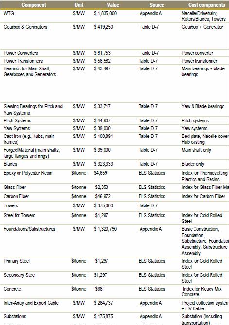
Table D-8. Cost Assumptions Used to Estimate Component and Material Market Values
A/s (2010 and 2011), Tetra Tech (2010)
Navigant. 2014. Offshore Wind Market & Economic Analysis Underlying Data. U.S. Department of Energy.
The U.S. offshore wind industry is transitioning from early development to demonstration of commercial viability. While there are no commercial-scale projects in operation, there are 14 U.S. projects in advanced development, defined as having either been awarded a lease, conducted baseline or geophysical studies, or obtained a power purchase agreement (PPA).
Globally, offshore wind projects continue to trend farther from shore into increasingly deeper waters; parallel increases in turbine sizes and hub heights are contributing to higher reported capacity factors. While the trend toward greater distances helps reduce visual impacts and public opposition to offshore wind, it also requires advancements in foundation technologies and affects the logistics and costs of installation and maintenance.
The average turbine size for advanced-stage projects in the United States is expected to range between 5.0 and 5.3 MW.
While much of the focus in recent years has been on alternatives to the conventional monopile approach (due to various limitations), the advent of the extra-large (XL) monopile (suitable to a 45 m water depth) may have somewhat lessened the impetus for significant change.
U.S. offshore wind development faces significant challenges: (1) the cost competitiveness of offshore wind energy;2 (2) a lack of infrastructure such as offshore transmission and purpose-built ports and vessels; and (3) uncertain and lengthy regulatory processes.
Key federal policies expired for projects that did not start construction by year-end 2013: the Renewable Electricity Production Tax Credit (PTC), the Business Energy Investment Tax Credit (ITC), and the 50 percent first-year bonus depreciation allowance.
Expected installed costs for a 500 MW farm are $2.86 Billion or $5,700/kW.
In terms of coal, Navigant analysis reveals executed and planned coal plant retirements through 2020 of nearly 40 GW.
these deeper waters and longer distances present new challenges and opportunities for foundations, drivetrains, installation logistics, and operations and maintenance (O&M). Time will tell how well initial U.S. projects align with those global trends in light of region-specific wind resource and seabed conditions. This section presents an overview of the global offshore
There are approximately 7 gigawatts (GW) of offshore wind installations worldwide.
new capacity installed in 2013, most is attributable to four countries – Belgium (192 MW of new capacity), Denmark (400 MW), Germany (230 MW) and the United Kingdom (812 MW) – with the U.K. comprising 47 percent of 2013 additions globally.
Uncertain political support for offshore wind in European nations and the challenges of bringing down costs mean that the pace of capacity growth may level off in the next two years (Global Wind Energy Council [GWEC] 2014).
Table 1-1. Summary of Cumulative Installed Global Offshore Capacity through
WindFloat Pacific (WFP) Seattle, Washington-based Principle Power has proposed to install five semi-submersible, floating foundations outfitted with Siemens 6 MW, direct-drive offshore wind turbines. The project will be sited 15 miles from Coos Bay, Oregon in approximately 350 meters of water. Principle Power maintains that the WindFloat design will be more cost-effective than traditional offshore wind foundations because the entire turbine and floating foundation will be built on shore and installed with conventional tug vessels. The innovations associated with the WindFloat design include the following: ? Static and dynamic stability provide pitch performance low enough to use conventional (i.e., fixed-foundation), commercial offshore turbines ? The design and size allow for onshore assembly and commissioning ? The shallow draft of the semi-submersible foundation allows the assemblies to be sited, transported (via wet tow), and deployed in a wide range of water depths WindFloat’s semi-submersible foundation includes patented water entrapment (heave) plates at the base of each of three vertical columns. A closed-loop, active water ballast system moves water between the columns in the semi-submersible foundation in response to changes in wind force and direction. This allows the mast to remain vertical, thereby optimizing electricity production.
the long-term capital cost increase has been a function of several trends: a movement toward deeper-water sites located farther offshore; increased siting complexity; and higher contingency reserves that result from more limited operational reserves and greater uncertainty when working in the offshore environment (Chapman et al. 2012).
Depth and Distance from Shore
The global trend toward deeper water sites and greater distances from shore continued in 2013, both for completed projects and those newly under construction. With this trend comes increased costs tied to more complex installation in deeper waters, longer export cables (and subsequent line losses), and greater distances for installation and ongoing O&M vessels to travel.
For commercial-scale projects with capacity additions in 2013, the average water depth was about 15 meters, and the average distance from shore was 13 miles.
Vestas V164 8 MW prototype turbine installed in early 2014 has a rotor diameter of 164 meters, greater than any other turbine currently slated for construction through 2015. Its 80 meter blades use a design that abandons the company’s conventional central spar approach (wherein a central “backbone” runs the length of the blade and absorbs most of the structural loads). Instead, the blades incorporate a “structural spar” design that
Samsung S7.0-171 prototype turbine was commissioned in June 2014 at the Fife Energy Park in Scotland (PE 2013). The blade, developed by SSP Technology, also uses carbon and holds the current record for the longest blade ever produced at 83.5 meters (171-meter rotor diameter). The blade is part of Samsung’s 7-MW turbine, which is expected to be deployed in 2015 in South Korea’s first offshore wind plant (CompositeWorld 2013).
Monopiles have historically dominated the offshore wind market. In the U.S., the Cape Wind project has committed to using monopiles to support its 3.6 MW turbines. Despite their popularity and familiarity, these large steel pipes (with diameters between 3 and 7 meters) have recently been challenged as increasing water depths and larger turbines sizes pose challenges related to installation logistics, turbine design, and material costs.
Despite the potential benefits of these XL monopiles, there may still be challenges to overcome. For example, as they continue to increase in size, these larger foundations may encounter limitations in the vessels that can handle their greater size, weight and diameter, which exceed the capabilities of available piling hammers (IHC Merwede 2012, A2SEA 2014).
Multi-piles Lead to Broader Diversity in Design Approaches
For sites in deeper water (from 25 to 60 meters), or with 5 MW and larger turbines, developers have historically shown a preference for multi-pile designs (e.g., jackets and tripods). Jacket structures derive from the common fixed-bottom offshore oil rig design, relying on a three- or four-sided lattice-framed structure that is “pinned” to the seabed using four smaller pilings, with one in each corner of the structure (EWEA 2011; Chapman et al. 2012). The tripod structure utilizes a three-legged structure assembled from steel tubing with a central shaft that consists of the transition piece and the turbine tower (EWEA 2011). Like jackets, the tripod is also pinned to the seabed with smaller pilings.
it is likely that multi-pile substructures will continue to gain market acceptance, especially in water depths greater than 30 meters and at sites with challenging subsea soil conditions.
Recent experience suggests that conventional gravity-base designs may encounter difficulties in water depths greater than 15 meters due to several key challenges:
- long fabrication durations to allow for curing of concrete;
- high dredging requirements to achieve precise seabed preparation;
- reliance on expensive heavy-lift vessels; and
- the installation schedules’ high sensitivity to weather conditions.
Shift to HVDC Transmission Lines
As projects have moved further from shore, industry interest in HVDC export cables has increased, as they create lower line losses than conventional HVAC lines. Various complications, however, have slowed the anticipated shift to HVDC over the past few years. For example, Siemens has suffered from significant write-offs (totaling €1.1 billion since 2011) for over-budget transmission HVDC projects intended to link offshore wind farms in the North Sea to the land-based grid (Webb 2014).
Notably, the AC-to-DC converter stations for these projects are enormous, expensive, and present some new logistical challenges for their construction installation. In June 2014, for example, Drydock World announced the completion of the DolWin beta HVDC converter platform, one of two major components for TenneT’s 900-MW DC offshore grid connection in the North Sea. The structure, an adaptation of semi-submersible offshore oil and gas rigs, weighs approximately 23,000 metric tonnes. The top-side equipment alone weighed 10,000 tonnes, and its installation onto the substructure established a new record for heavy lifts. From its construction port in Dubai, the converter station will be loaded onto a heavy lift vessel for transportation to its commission port in Norway, after which it will be towed to the project site. (Marine Log 2014). In response to these recent cost overruns and logistical challenges presented by conversion to HVDC, some developers are opting to reduce risk by instead running increasingly longer distances with AC export cables (Simon 2014).
In the U.S., the two most advanced U. S. projects, which are relatively near shore compared to the larger European projects, will rely on conventional AC transmission. Deepwater’s Block Island project will use a 34.5-kV AC export cable, while Cape Wind, plans to use a 115 -kV AC export cable (Tetra Tech 2012; DOE 2012a).
Developers and contractors have been working to create solutions to the limited availability of vessels, which could represent a potentially limiting factor for the growth rate of the U.S. offshore wind market. The offshore wind project life cycle includes four general phases: pre-construction, construction, project O&M, and decommissioning. Each of these phases comprises various types of services, each typically requiring one or more unique types of vessel.14 Recent developments in North America have focused primarily on vessels used during construction and O&M. As global demand for vessels to serve the offshore wind market has increased, vessel suppliers and construction teams have sought to reduce the time required for installation and for transferring foundations, towers, turbines, and blades to sites farther from shore. In particular, newer jack-up vessels are demonstrating several key trends, including the following:
- Increasing deck space to facilitate storage of more and larger turbine components per trip
- Greater crane capacities (i.e., lifting capacity typically greater than 1,000 metric tonnes and hook heights in excess of 105 meters) to lift increasingly large turbine and substructure components
- Increasingly advanced dynamic positioning (DP2 and DP3) systems to increase operational efficiency and safety
- Longer jack-up legs to enable lifting operations in deeper waters
- Greater ability to continue operations in increasingly severe sea states (i.e., wave height limit of at least two meters) to minimize construction downtime
While crane lifting capacity continues to increase, the maximum lifting height appears to be a new key limitation in selecting the construction vessel, as the trend toward larger rotors and taller towers also continues (Hashem 2014). In addition, the impact of moving to XL monopiles is not yet fully understood by the vessel industry; however, there are a few existing vessels capable of lifting these extra-large monopiles’ extreme weights.
The full spectrum of vessels that may be needed at various points in the offshore wind life cycle is discussed in the previous iteration of this annual market assessment, published in October 2013.
16“Platform jacket” is defined as “a single physical component and includes any type of offshore exploration, development, or production structure or component thereof, including platform jackets, tension leg or SPAR platform superstructures (including the deck, drilling rig and support utilities, and supporting structure), hull (including vertical legs and connecting pontoons or vertical cylinder), tower and base sections of a platform jacket, jacket structures, and deck modules (known as “topsides”).
Other strategies being pursued include bottom-fixed foundations that are floating or semi-floating during transit to the installation site. For example, Freshwater Wind’s Shallow Water Wind Optimization for the proposed Great Lakes project relies on semi-floating, gravity-based foundation technology to eliminate the need for installation vessels during foundation installation. Note, however, that these projects would still require “traditional” jack up vessels to install the turbines.
A thriving U.S. offshore wind market will likely require the development of a more robust domestic fleet.
However, a general lack of O&M data for the still relatively young offshore wind industry (most turbines are still under warranty) make it difficult to draw any broad conclusions about the expected long-term costs and trends of O&M offshore wind farms.
Table 3-2. 2014 Detailed Cost Breakdown Cost (2011$) Cost % of Total (2011$ per Capital kW Cost Equipment Costs Turbine Costs $917,500,000 Foundation & Substructure $206,545,000 Collection System $78,490,000 HV Cable, Converter, & Substations $349,109,000 Labor Costs1 Foundation & Substructure Installation Labor $309,828,000 Project Management (Developer/owners $8,500,00 management costs) Development Costs Insurance During Construction $67,000,000 Development Services (Engineering, Legal, PR, $28,900,000 Permitting) Ports & Staging $45,000,000 Erection/Installation (equipment services only) $301,337,000 Air & Marine Transportation $79,890,000 Other Costs Decommissioning Bonding $100,000,000 Interest During Construction $165,843,000 Due diligence, Reserve Accounts, Bank Fees $163,331,000 Miscellaneous $17,394,000 Total Construction Cost2 $2,860,701,000 Source: Navigant analysis
an increased pro-nuclear attitude in the United States, potentially as a way to meet CO2- reduction targets, could reduce offshore wind activity in the United States if the levelized cost of new nuclear plants were to be more attractive than that of offshore wind. In early 2012, the United States Nuclear Regulatory Commission approved the construction license for four new nuclear reactors, two in South Carolina and two in Georgia. A fifth reactor is under construction in Tennessee. These would be the first nuclear reactors built from scratch in the last 30 years. If these reactors are successfully completed and become operational, their impact on the future of offshore wind in the United States is unclear. There is also uncertainty around the expected LCOE from these new nuclear plants, as the nuclear industry has not had a strong track record of meeting projected costs and schedules.
Figure 4-2. U.S. Power Generation Capacity Additions by Fuel Type 70
In recent years, some electric utilities in the U.S. have announced plans to retire coal-fired power plants or to convert them to natural gas. There are multiple factors involved in these retirement decisions. Many of the U.S.’s coal-fired power plants are over 50 years old and expensive to continue to operate and maintain. Complying with environmental requirements, such as the U. S. Environmental Protection Agency’s (EPA’s) mercury and air toxics standards can also be costly. Additionally, the rule submitted by the Environmental Protection Agency in June of 2014 to require a 30% reduction in CO2 emissions from existing power plants from 2005 emission levels by 2030 will likely impact retirement plans for existing coal generators. Navigant analysis reveals actual and announced retirements of nearly 40 GW through 2020. There is significant uncertainty in the projection of planned retirements before 2030 due to Section 111 regulations proposed under the Obama Administration’s Climate Action Plan. While the reduction in generation capacity created through coal plant retirements will certainly not be filled entirely by a variable-output resource such as wind, continued coal plant retirements could play a role in increasing the demand for offshore wind plants in the U.S.
U.S. solar installations reached record levels in 2013, accounting for nearly 30 percent of all new electricity generating capacity installations (SEIA 2014). U.S. onshore wind installations fell during 2013 due to the uncertainties in federal tax incentives at the end of 2012.
Wind turbine towers require significant quantities of steel, while foundations may require concrete and/or steel. Since towers represent about 7-8 percent of the cost of an offshore wind farm and the foundations and substructures represent about 22-25 percent (Navigant 2012), the level of construction activity in the United States outside of the offshore wind sector could impact the price of offshore wind power. Figure 4-4 shows the evolution of commodity prices since 2002, which is a trend of generally increasing (and volatile in the case of steel) prices.
Manufacturing 4.5.1 Change in Manufacturing of Products That Utilize Similar Types of Raw Materials as Offshore Wind
The manufacturing sector similarly uses many of the same raw materials as offshore wind. The manufacture of automobiles, heavy equipment, and appliances, for example, requires significant amounts of steel, a material used in wind turbine towers and offshore foundations. Manufacturing sectors such as aerospace, automotive, and marine vessels use composite materials similar to those used in wind turbine blades. Finally, rare earth materials such as neodymium are used in applications such as the permanent magnets that are used in certain types of electric motors and electrical generators, including those in many direct drive wind turbine generators. The DOE (DOE 2010) estimates that supply situation for rare earth oxides of neodymium and dysprosium will be “critical” not only over the short term (2010- 2015) but also over the medium term (2015-2025). The supply risk for praseodymium was characterized as “not critical”. Criticality matrices from this report are shown in Figure 4-5.
A 2012 report from the Massachusetts Institute of Technology’s Materials Systems Laboratory agrees that neodymium and dysprosium will face supply challenges in the coming years (Alonso et al. 2012). If the supply situation for rare earth metals remains tight and prices rise, so could the cost of offshore wind production.
Change in Demand for Subsea Cable-Laying Vessels
The specialized vessels that are appropriate for subsea cable-laying are relatively few in supply and high in demand (Navigant Research 2012). Not only are these vessels in high demand in Europe for offshore wind projects; many of them are also used to lay subsea cable for the telecommunications industry. An increase in deployment of subsea cables by global telecommunications companies could increase the development costs of offshore wind farms.
Cost-Competitiveness of Offshore Wind Energy Capital costs for the first generation of U.S. offshore wind projects are expected to be approximately $6,000 per installed kW, compared with approximately $1,940 per installed kW for U.S. land-based wind projects in 2012 (Wiser and Bollinger 2013). Offshore projects have higher capital costs for a number of reasons, including turbine upgrades required for operation at sea, turbine foundations, balance-of-system (BOS) infrastructure, the high cost of building at sea, and O&M warranty risk adjustments. These costs remain high because the offshore wind industry is immature and learning curve effects have not yet been fully realized. There are also a number of one-time costs incurred with the development of an offshore wind project, such as vessels for turbine installation, port and harbor upgrades, manufacturing facilities, and workforce training. Offshore wind energy also has a higher LCOE than comparable technologies. In addition to higher capital costs, offshore wind has higher O&M costs as a result of its location at sea. Higher permitting, transmission, and grid integration costs contribute to this higher cost of energy, which can be
Infrastructure Challenges
Offshore wind turbines are currently not manufactured in the United States. Domestic manufacturing needs to be in place in the United States in order for the industry to fully develop. The absence of a mature industry results in a lack of experienced labor for manufacturing, construction, and operations. Workforce training must therefore be part of the upfront costs for U.S. projects. The infrastructure required to install offshore wind farms, such as purpose-built ports and vessels, does not currently exist in the United States. There is also insufficient capability for domestic operation and maintenance.
The absence of strong demand for offshore wind in the United States makes it difficult to overcome these technical and infrastructure challenges. In order to develop the required infrastructure and technical expertise, there must first be sufficient demand for offshore wind, and that is not expected in the near term due to the high cost of offshore wind and the low cost of competing power generation resources, such as natural gas.
Regulatory Challenges A.3.1 Permitting
Offshore wind projects in the United States are facing new permitting processes. After issuing the Final Rule governing offshore wind leasing on the Outer Continental Shelf (OCS) in 2009, the Minerals Management Service (MMS)—now BOEM—staff estimated that the lease process might require three EISs and may extend seven to nine years.
Construction and operations plans proposing the installation of renewable energy generation facilities would be subject to additional project specific environmental reviews.
A number of state and federal entities have authority over the siting, permitting, and installation of offshore wind facilities. Cognizant federal agencies include BOEM, the U.S. Army Corps of Engineers (USACE), the EPA, the FWS, the National Oceanic and Atmospheric Administration (NOAA) National Marine Fisheries Service, and others.
REFERENCES
A2SEA. (2014). Big foundations, big challenges. A2SEA News. November 11, 2013. http://a2seanews.editionmanager.com/2013/11/11/big-foundations-big-challenges/
Andresen, T. and Nicola, S. (2012). RWE Sees German Climate Goals Threatened by Grid Delays: Energy. Bloomberg Online. July, 2012. http://www.bloomberg.com/news/2012-07-03/rwe-sees-germanclimate-goals- threatened-by-grid-delays-energy.html
Backwell, Ben. (2013). MHI to supply 700 7MW turbines to UK R3 projects – official. Recharge News. February 28, 2013.
Campbell, Shaun. (2013). “Setback for Deepwater Wind’s Block Island project. WindPower Offshore. August 6, 2013. Accessed September 16, 2013. Available at: http://www.windpoweroffshore.com/article/1194228/setback-deepwater-winds-block- island-project.
Composite World. (2013). DIAB core going into 83.5m long wind turbine blade. June 9, 2013.
Deign J (2020) So, What Exactly Is Floating Offshore Wind? Greentechmedia.com
EWEA. (2011). UpWind – Design limits and solutions for very large wind turbines. March 2011. Accessed September 16, 2013. Available at:
http://www.ewea.org/fileadmin/ewea_documents/documents/upwind/21895_UpWind_Repor t_low_ web.pdf.
Federal Maritime and Hydrographic Agency (BSH). (2013). Standard: Investigation of the Impacts of Offshore Wind Turbines on the Marine Environment (StUK4). BSH-Nr. 7003. http://www.bsh.de/en/Products/Books/Standard/7003eng.pdf
Foster, Martin. (2014). “Fukushima 7MW platform complete.” Wind Power Offshore. http://www.windpoweroffshore.com/article/1298310/fukushima-7mw-platform-complete
Grandoni D (2020) New Jersey aims to lead nation in offshore wind. So it’s building the biggest turbine port in the country. Washington Post.
Hamilton, B. (2011). “Offshore Wind O&M Costs, Trends, and Strategies.” EWEA Offshore 2011. Amsterdam, The Netherlands, 7 pp. Hashem,
LORC. (2011). The Gravity Based Structure – Weight Matters. Lindoe Offshore Renewables Center. Munkebo, DK. http://www.lorc.dk/offshore- wind/foundations/gravity-based.
OceanWind. (2010). Offshore Wind Experiences: A Bottom-Up Review of 16 Projects. 08 April 2010. %20A%20bottom-up%20review%20of%2016%20projects%20(Ocean %20Wind).pdf
“Giant 7MW Fife offshore turbine completed.” Institution of Mechanical Engineers. http://www.imeche.org/news/engineering/giant-7mw-fife-offshore- turbine-completed Peire, K.; Nonnneman, H.; Bosschem
SSP Technology. (2013). World’s longest rotor blade for wind turbine – core materials. http://www.ssptech.dk/nyheder.aspx? Action=1&NewsId=116&PID=357&World’s+longest+rotor+bla de+for+wind+turbine+- +core+materials
US. Department of Energy (DOE). (2010). Critical Materials Strategy. Washington, DC: U.S. Department of Energy.
http://energy.gov/sites/prod/files/edg/news/documents/criticalmaterialsstrategy.pdf
Webb, Alex. (2014). Siemens Inks $2.1 Billion Deal for 600-MW Dutch Offshore Wind Project. Renewable Energy World. May 15, 2014. http://www.renewableenergyworld.com/rea/news/article/2014/05/siemens-inks-2-1- billion-deal-for600-mw-dutch-offshore-wind-project
Wiersma, F., Grassin, J., Crockford, A., et. al. (2011). State of the Offshore Wind Industry in Northern Europe: Lessons Learnt in the First Decade.” Ecofys Netherlands BV. http://www.northsearegion.eu/files/repository/20120320110429_PC StateoftheOffshoreWindIndustryinNorthernEurope-Lessonslearntinthefirstdecade.pdf
3 Responses to Offshore wind turbines: Expensive, risky, and last just 15 years